pre engineered building
In structural engineering, a PreEngineered Building (PEB) is designed by a PEB supplier or PEB manufacturer, to be fabricated using best suited inventory of raw materials available from all sources and manufacturing methods that can efficiently satisfy a wide range of structural and aesthetic design requirements. Within some geographic industry sectors these buildings are also called pre-engineered metal buildings (PEMB) or, as is becoming increasingly common due to the reduced amount of pre-engineering involved in custom computer-aided designs, simply engineered metal buildings (EMB).

Components of PEB
Pre Engineered Buildings consist different steel structural member which are as follows,
- Primary Frame:
Primary framing of a PEB is an assembly of builtup I-Shaped steel members & that framing consist trusses or castellated beams etc. - Secondary Structural Elements:
It is actually Cold Formed Members, which can be in diff. shapes like “Z”, “C” etc. In general known as “Purlins”. - Roof & Wall Panels :
Tin shades & Curtain Wall made of Glass & Roll-formed steel sheets usually comes in this category. - Sandwich Panels:
Sandwich Panel is made of three layers , in which a non-Aluminum Core is inserted b/w two aluminum sheet. - Other Accessories:
Mezzanine floors, Bolts, Insulation, etc.
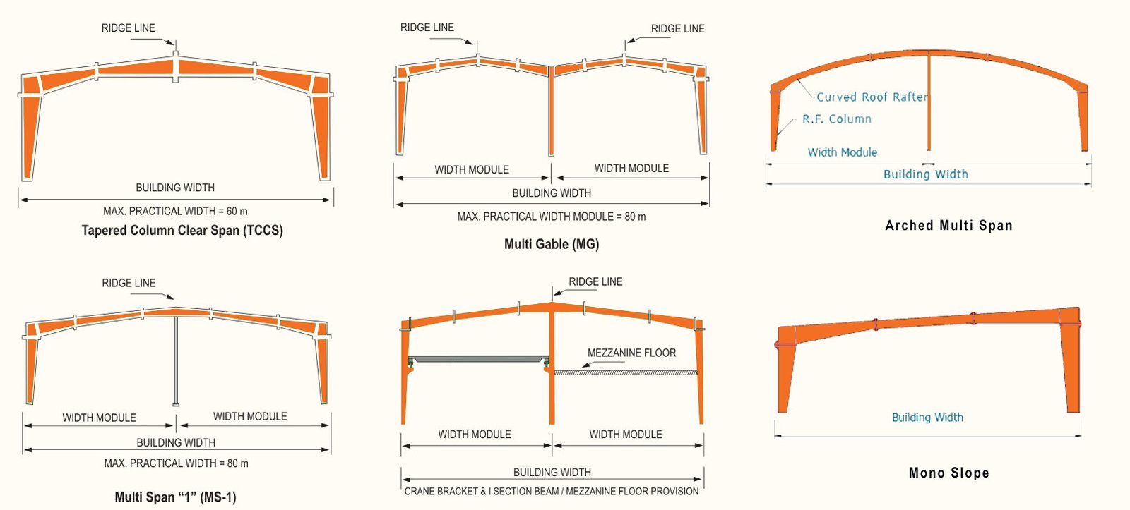
Types of Span

Design Methodology
- Method Used :
Stiffness Matrix Method - Standard Code used :
- AISC
- ASCE
- IS : 800
- Software used :
Staad.Pro v8i, ETABS, RAM Steel - Load Considerations & their Calculations :
Loads considered in the PEB design are same as for general building structure. These are as follows ,- Dead load Calculations :
It includes Self Wt. of Purlins , Roof & Wall Sheeting , insulation material & other structural component. - Live / Imposed Load Calculations :
It should be Considered as per given in IS 875 (Part 2 ) for diff. type of - Wind Load Calculations :
Consider the Basic wind Speed as per Area of that particular structure. Design wind Pressure is calculated as per IS 875 (Part 3) . Wind Load on Roof can be UDL & calculation for this can be done as per IS875(Part 3) - Seismic Load Calculations :
Earthquake Loads affect the design of structure in areas of great seismic activity. The seismic load can be calculated as per IS 1893-2002(Part 1). - Other Moving Loads :
It can be Moving EOT Crane load or Mono Rail etc.
- Dead load Calculations :
- Load Combinations :
As per IS 1893 – 2002 (Part 1)- 7(DL ± LL)
- 7(DL ± EL)
- 3(DL + LL ± EL)
- Mechanism :
For diff. Load Combinations structure should be checked by considering Internal work equal to External work and We will consider the following Mechanism,- Beam Mechanism
- Sway Mechanism
- Gable Mechanism
- Combined Mechanism
- Checks Made :
- Effect of Axial Force :
Max. Load should be checked with allowable load bearing of the section. As, Max. Axial Force in Column/Axial Load causing yielding < 0.15 - Check should also be made for Local Buckling of Flanges & Webs.
- Check for the Effect of Shear Force :
Shear Force at the end of the Girder should be less than the Max. Shear Capacity.
- Effect of Axial Force :
- Design Procedure :
It consist some steps, which are as follows,- Based on the geometry, set up section sizes and brace locations.
- Loading Calculations :
Specify the Load case & load combinations for designing of the framed steel structure. - Calculate S.F. & M. for each load case detail
- By using the Standard Codes, check and compare the calculated stress with the allowable or Permissible Shear Stress & Bending Stress values.
- Design the optimum Splice Location.
- Made check for predicted section that it satisfy or fail for any loading conditions.
- Now, by ending the design an analysis is run to achieve flange bar optimization.
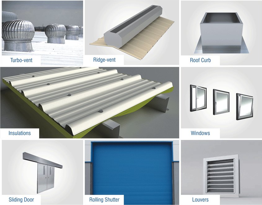
Building Accessories
